DESIGN OF EXTRUSION BLOW MOLDS
The actual design of a blow mold will be guided by the standard data available to adapt the mold to the machine and the applicable process. The mold cavities will be replicas of the exterior surface of the blownware product with the essential material shrinkage added to the product dimensions. A typical mold is shown in Fig. 1.
 Fig. 1.
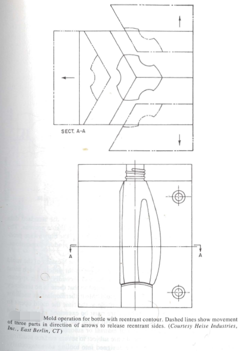
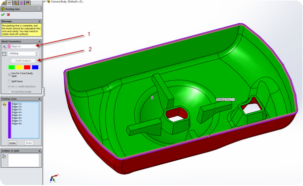
The blow mold designer’s initial consideration is the location of the mold parting line. This is determined first by the shape of the article which must be molded so it can be ejected from the mold, and secondly, by its appearance. The mold parting line should be positioned so that there is no tendency for the molded piece to “lock” in the mold. Most thermoplastics used for blow molding are sufficiently hot and pliable at the time the mold opens to permit some negative relief or hook. Care must be exercised in the amount of hook used, for an excessive amount will cause the finished part to stay in one mold half. While some form of manual or automatic ejection can be employed, parts with excessive hooks are subject to severe surface scuffing-Intentional hooks can sometimes be designed into tooling advantageously-For example, opposite and opposed hooks which create a force couple at t e time of mold opening will spin the molded article and allow it to eject freely.
The mold parting line should be hidden in the container design if at all possible. It should also be kept off surfaces which will subsequently be decorated with silk-screen, hot stamp, or paper labels. Any one of these labels will show some irregularity or flaw caused by the uneven surface associated with the mold parting line. The quality and speed of molding should not be sacrificed for appearance design. On a square bottle, for example, it might appear advantageous esthetically to hide the parting line on two corners by having it run diagonally across the bottle. A closer analysis will show the hidden parting line is not worth the irregular wall distribution which will result from the pinch-tube method. The base corners perpendicular to the parting line will be much thinner than those on the parting line, and will cause bottom distortion through uneven cooling.

With the parting line established, the extremities of the mold are selected within the limitations of the blow molding machinery on which the mold will be used. At this time the cavity is positioned most advantageously relative to the extruded parison. For most symmetrical items the cavity and parison centerlines coincide and are parallel. There are, however, times when the wall distribution of the final molded part can be improved by tipping the mold cavity centerline relative to the parison centerline.
