Design of the Molded Part
The following factors can significantly influence the design of the molded part:
- Flow properties of the melt,
- Solidification behaviour,
- Pressure transfer in the cooling-down melt,
- Molecular and fiber orientation,
- Shrinkage and its dependence on process parameters, on the gate position and on the direction of measuring,
- Warpage, which increases remarkably through fiber reinforcement.
- When designing, it has to be especially taken into account:
- Demoldability,demolding draft angle,
- Permissibility of weld lines,
- Permissibility of marks by gates, ejectors, sliders and splits,
- Surface structure,
- Required tolerances.
The area around the gate has normally far more molecular orientations than other areas. Additionally, there is often an overloading due to a too high melt compression or too long holding pressure. This forms an area very liable to fracture. The practical experience coincides with the fact that two thirds of fracture lines pass through the gate. The gate position is often indicated by stress crack lines
Important to consider the following fundamental rules:
- No gates and weld lines in high-stressed areas and edges!
- Avoid wall thickness differences. The ideal injection molded part has equal wall thickness.
- If mass concentrations cannot be avoided, they have to be positioned as close as possible to gate. Figure 1.9 shows a negative example.
- Minimize wall thicknesses and only as big as absolutely necessary!
- Optimize wall thicknesses, position and number of the gates to result in a uniform and inclusion- free flow front progress. Therefore, it is essential to perform a rheo-logical analysis with finite elements. Several experienced simulation programs for example Cadmould or Moldflow can be used for this application.
- Avoid sharp inside edges.
- Use simplifications: Often a few minor design changes are enough to process without the use of sliders or jaws. This decreases the mold costs drastically.
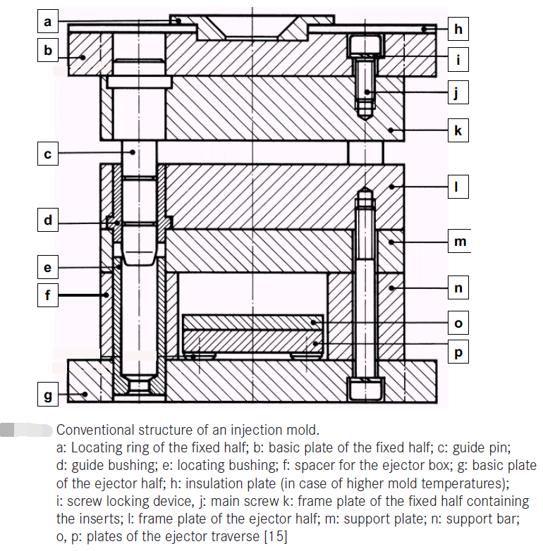
Conventional structure of an injection mold.

a: Locating ring of the fixed half; b: basic plate of the fixed half; c: guide pin; d: guide bushing; e: locating bushing; f: spacer fo「the ejector box; g: basic plate of the ejector half; h: insulation plate (in case of higher mold temperatures); i: screw locking device, j: main screw k: frame plate of the fixed half containing the inserts; I: frame plate of the ejector half; m: support plate; n: support bar; o, p: plates of the ejector traverse.The mechanical and thermal design can also be done using different CAE programs. The integration of cooling channels allows a detection of “hot spots” in the mold. These “hot spots” are determining the cooling time and have to be eliminated
The tolerances for plastic molded parts are standardized in DIN 16901. However, in practice, narrower tolerances are demanded and achieved.
