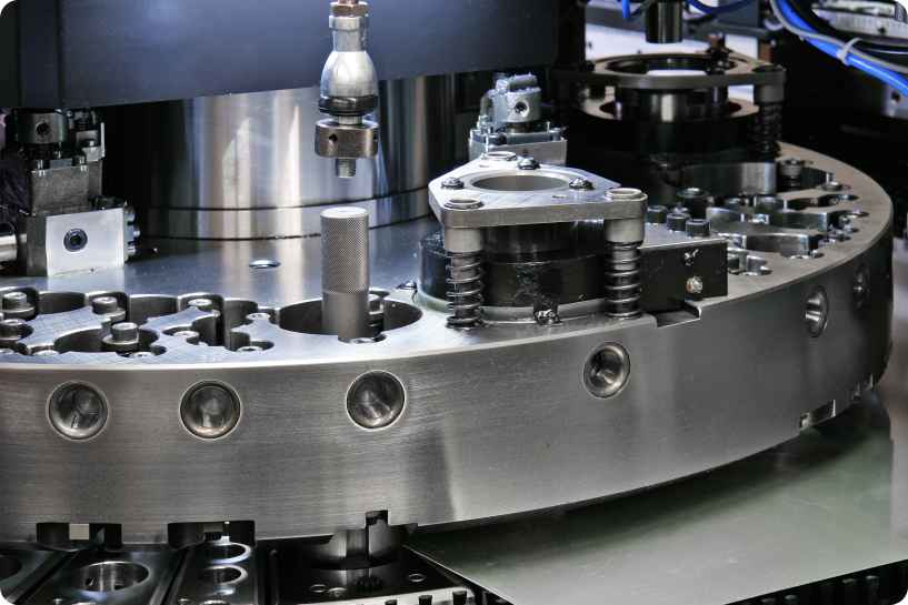
While the hand duplicator or copy milling machine is still the backbone of the mold-making industry because of its ability to cut just about any shape with a high degree of accuracy, it is slow and requires a highly skilled operator in order to obtain the optimum quality and accuracy of cut. This hand duplicator has given way to the automatic duplicator. Even more recently, it has given way to the numerically-controlled (NC) or computer numerically-controlled (CNC) machine, because automatic duplication or computer control will increase productivity as well as provide more accurate contours needing less handwork to finish to final surface and dimension.
The automatic duplicator with its multiple heads can cut as any duplicates as there are cutting heads. The path of the cut is controlled by a stylus which traces over a pattern of the desired shape. The stylus is connected, in turn, to a sensing device which will transmit to the hydraulic °r electronic control units the information they need to direct the machine to cut the correct shape of the reproduction. In all instances, some movement of the stylus is required to transmit a change in direction to the tool# path. This fact, together with the necessity for the stylus diameter to be larger than the cutter diameter, eliminates this method of duplication when fine detail is required.

Numerically controlled machinery has been available for a number of years for two and two-and-one-half axis machining. Now these machines have added controls with their own computer to enhance their flexibility of operations. The most recent technological improvement has been the use of computer graphics to program or direct the operations of the NC machines. This recent technology is the so-called CAD/CAM system (CAD is the acronym for Computer Aided Design; CAM is the acronym for Computer aided Manufacturing). In reality, the mold designer uses a CRT (cathode-ray tube) on which to draw what would normally be drawn with pencil and paper. Figure 11.33 illustrates this CRT technique. That which is drawn on the CRT can be reproduced at any desirable size or scale to make the familiar “tracing” associated with drafting. In the case of CAD, this reproduction is called “plotting.” The important point here is this: whatever shape can be drawn or modeled on the CRT can be reproduced by the NC or CNC machine within the normal limitations of tool geometry. It should be obvious that the potential for the CAD/CAM system of mold-making is enormous. The overall cycle time to make a mold can be greatly reduced by eliminating the need for a three-dimensional pattern, by increasing, the handwork on a mold, and by increasing the accuracy of the duplication. Many NC machines performing multiple tool operations (using automatic tool changers) are capable of unattended operations on a 24-hour basis. However, someone who knows the “shut-down procedure,,should e nearby,for that rare occasion when “automatic” is not good enough to Prevent catastrophe.
