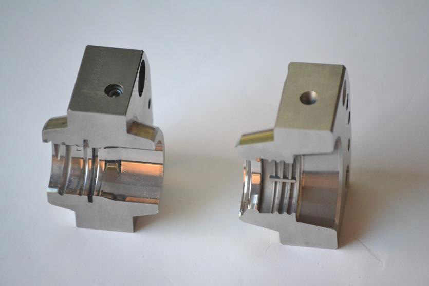
neck insert

In most cases, inserted pieces are designed for the neck and base areas of the mold as noted previously. The neck insert cavity component is a replica of the finished product in the neck area, and in addition, carries a configuration above the top of the finished neck suitable for the particular blowing machine. Generally this configuration provides a reduction from the neck diameter to a small diameter which fits the blow pin on the blowing machine. Some blowing machines have a movable blow pin that moves into the neck end of the blown object after the mold closes and completely finishes the part to size in this area. This operation eliminates subsequent trimming operations. For this finished neck process in the pinch-tube method of blow molding, a hardened piece must be added to the neck insert to prevent excessive wear from the movable blow pin. If the extruded tube from which the article will be blown is larger in diameter than the^ diameter of the neck insert cavity, then a pinch relief must be provided for the excess plastic which will flash. With a pinched neck, threads, if used, can be made either continuous or interrupted. The interrupted thread does not cross the parting line, leaving a smooth surface from which to remove the residual plastic flash. The disadvantage of this type o thread is the reduced engagement possible between a molded article and closure which, in some circumstances, might cause faulty sealing. Maximum closure torque and superior sealing properties are desired, t ^ thread is made continuous and the pinch relief is cut around each thread at the parting line.

The neck end of any blown piece usually has heavy wall sections thus making it desirable to provide a maximum amount of cooling in the neck insert. Cooling channels having a large surface area and small cross-section area are the most desirable, as noted previously. Coolant inlets and outlets are located for accessibility within the design of the blow molding machine. For a minimum number of fittings and hoses, it is sometimes preferable to connect two or more parts of the mold in series rather than have individual inlet and outlet lines connected to the mold body, neck, and base inserts.
Another effective method of minimizing connections is by the use of a mold back plate which serves as a manifold. The coolant then enters the back plate at one end and enters each of the mold parts through some suitable seal such as an “O” ring. The coolant is then discharged through separate holes in a similar manner.
The base insert carries the pinching edges which seal the end of the tubular parison,and in the usual container, the base indentation or pushup, the base insert should be sufficiently high to accommodate the variations in parison length associated with variations or surging within the extruder.
For molds utilizing some mechanical means of removing the base tab formed by the pinch tube process during the molding cycle, the height of base insert is kept to a minimum. This minimum height reduces the frictional area over which the tab must be pulled by the removal mechanism. the base insert is contacting thick and hot sections of Plastic. The cooling channels should therefore be kept close to the parting Surface which is the area needing greatest heat absorption.
The heavy sections of plastics material, much distortion can take place during cooling. For. This reason allowances must be made for defects which might affect the function of the blown article. For containers having a pushup, the height of the curvature must be increased to allow for its sinking, a correction is also usually incorporated that will insure stability of the container on its base. This latter correction consists of cutting three or four deeper sections in the base inserts that will provide projections on which the container will ultimately set.
